Power Inductors Shielded - SMT |
Power Inductors (OLD) | Back |
Power Inductors Shielded - SMT |
Power Inductors (OLD) | Back |
 |
|
QPIH1205 QPIH1205MP Series |
| Falco Part Number |  RoHS Part Number RoHS Part Number |
Inductance (çH) | Saturation Current(A) Isat (at 25¯C)3 |
Rated Current(A) D T=40 ÝC4 |
DC Resistance (mW) max. (at 25¯C) |
|
|---|---|---|---|---|---|---|
| Li (at 25¯C)1 | Lrat (at 25¯C)2 | |||||
| QPIH1205 SERIES |
||||||
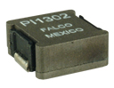
 PI1302 PI1302 |
PIL302 |
0.330 Ý25% | 0.310 | 46.0 | 30.0 | 1.42 |
| PI1305 |
PI13L5 |
0.550Ý25% | 0.530 | 40.0 | 25.0 | 1.50 |
| PI1306 |
0.800Ý25% | 0.730 | 37.0 | 20.0 | 2.20 | |
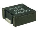
| PI1307 |
1.10Ý25% | 1.05 | 25.0 | 20.0 | 2.20 | |
| PI1311 |
1.80Ý25% | 1.66 | 19.0 | 15.0 | 3.30 | |
| PI1301 |
PI13L1 |
2.25Ý20% | 2.05 | 16.0 | 14.0 | 4.20 |
| PI1308 |
2.50Ý25% | 2.15 | 13.5 | 14.0 | 4.20 | |
| PI1304 |
4.70Ý20% | 4.45 | 12.0 | 10.5 | 8.00 | |
| QPIH1205MP SERIES |
||||||
| PI1401 |
PI1402 |
1.80Ý25% | 1.45 | 18.0 | 15.0 | 3.30 |
|
|
||||||
|
||||||
Power Inductors Shielded - SMT |
Power Inductors (OLD) | Back |
 |
|
QPIP1205 Series |